
Understanding how to identify parts on a circuit board is essential for anyone working with electronics. Whether you’re a hobbyist repairing a device or a professional troubleshooting complex systems, knowing the components and their functions can save time and prevent costly mistakes. This guide will walk through the key parts of a circuit board, helping readers gain the confidence to navigate and work with these intricate designs effectively.
Understanding Circuit Boards
Circuit boards serve as the foundation of most electronic devices. Knowledge of these boards leads to better repairs, efficient troubleshooting, and an understanding of electronic functionality.
What Is a Circuit Board?
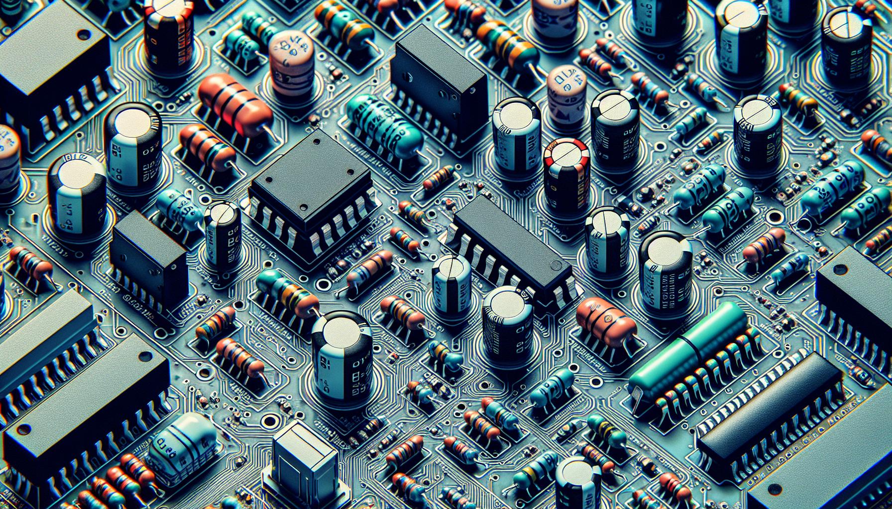
A circuit board, often referred to as a printed circuit board (PCB), is a flat board made of insulating material, typically fiberglass, with conductive pathways etched onto its surface. These pathways connect various electronic components such as resistors, capacitors, and integrated circuits, enabling them to communicate and function together. Circuit boards can vary in complexity; simple boards may only contain a few components while advanced ones may host hundreds to thousands of interconnected parts.
Common Types of Circuit Boards
Circuit boards come in several common types, each serving a unique purpose within electronic designs:
- Single-Sided Circuit Boards: These boards have components and circuits on just one side. They’re simple and cost-effective, ideal for low-complexity projects.
- Double-Sided Circuit Boards: Components are present on both sides of the board. They allow for increased circuit density and are common in a variety of consumer electronics.
- Multi-Layer Circuit Boards: These boards consist of several layers of circuits sandwiched together. They support more complex designs and can handle advanced functionalities often found in computers and smartphones.
- Flexible Circuit Boards: Made of flexible materials, these boards bend and conform to fit within compact spaces. They find application in devices requiring space-saving solutions, such as wearables and mobile phones.
- Rigid-Flex Circuit Boards: Combining rigid and flexible elements, these boards allow for intricate designs while maintaining durability. They’re used in aerospace and advanced medical devices.
Understanding circuit board types aids in identifying the right board for specific electronic needs, contributing to successful repairs and innovative designs.
Essential Components of a Circuit Board
Circuit boards contain essential electronic components, each serving a specific function. Understanding these components proves invaluable for anyone working with circuit boards.
Resistors
Resistors limit the flow of electrical current. They protect sensitive components from damage by ensuring that current levels remain within safe limits. Color codes on resistors indicate their resistance values, which is crucial for proper circuit design. Resistors come in various types such as fixed, variable, and special-purpose resistors.
Capacitors
Capacitors store and release electrical energy. They help to smooth out voltage fluctuations and provide energy during brief power interruptions. Capacitor markings indicate capacitance values, measured in farads, along with voltage ratings. Common types include ceramic, electrolytic, and tantalum capacitors, each chosen for specific applications in circuit design.
Integrated Circuits
Integrated circuits (ICs) contain multiple electronic components within a single package. They execute various functions, from processing signals to performing calculations. ICs are characterized by their pin configurations and markings, which indicate their function and operating specifications. Common types include microcontrollers, operational amplifiers, and memory chips, and they significantly reduce space and complexity in circuit design.
Tools for Identifying Parts
Different tools facilitate the identification of components on a circuit board. These tools help ensure accurate diagnostics and repairs.
Multimeter
A multimeter measures electrical properties such as voltage, current, and resistance. It helps identify faulty components by allowing users to check for continuity in circuits. Using a multimeter involves setting the device to the appropriate mode—ohm for resistance, volts for voltage, and amps for current. Accurate readings guide users in diagnosing issues and confirming component functionality.
Soldering Iron
A soldering iron is essential for repairing or replacing components. It heats up to melt solder, which connects electronic parts to the circuit board. Using a soldering iron allows users to easily remove damaged parts and solder in new components, ensuring reliable connections. Proper technique prevents damage to both components and the circuit board during the process.
Circuit Board Scanners
Circuit board scanners provide a comprehensive way to identify and analyze components. These handheld devices scan circuit boards and display detailed information about each part. They detect component types, values, and connections, simplifying the identification process. Scanners save time and reduce errors, making them invaluable tools for technicians and hobbyists alike.
Step-by-Step Guide on How to Identify Parts on a Circuit Board
Identifying parts on a circuit board requires a systematic approach. This guide outlines practical steps to clarify the process.
Visual Inspection
Visual inspection serves as the first step in identifying parts on a circuit board. Inspecting the board involves examining components for their physical characteristics. Users should look for:
- Component Types: Identify resistors, capacitors, integrated circuits (ICs), and diodes by their shapes and sizes.
- Markings: Check for alphanumeric codes printed on components, which typically denote values and specifications.
- Connections: Observe the connections of components to identify their location and links on the board.
This initial assessment helps in recognizing common parts quickly.
Using a Multimeter
Using a multimeter provides a reliable method for testing and identifying circuit components. The multimeter can measure several electrical properties, including:
- Resistance: Set the multimeter to the resistance mode and measure resistor values. This confirms resistance based on color codes.
- Voltage: Switch to the voltage mode to check for proper voltage levels across components. This determines the functionality of capacitors and other components.
- Continuity: Use the continuity test function to verify connections between points on the circuit board. It helps ensure complete pathways.
These measurements assist in diagnosing faulty components effectively.
Reference Diagrams
Reference diagrams support the identification process by providing detailed layouts of circuit boards. Users should consult:
- Schematic Diagrams: These diagrams show the electrical connections and components in a simplified format. They indicate how parts connect and interact.
- Component Layouts: These illustrations map out the physical placement of components on the board, allowing users to locate them accurately.
- Datasheets: Manufacturers often provide datasheets for components, detailing specifications, pin configurations, and usage instructions.
Utilizing these resources enhances comprehension of the circuit board’s structure and function.
Troubleshooting Common Issues
Identifying issues on a circuit board requires attention to detail and precise methods. Common problems often stem from faulty components, which can disrupt an entire device’s functionality.
Identifying Faulty Components
Identifying faulty components involves systematic evaluation. Start by inspecting components visually for signs of damage, such as burn marks or corrosion. Use a multimeter to test for continuity; a lack of continuity indicates a non-functioning component. Additionally, compare measurements with expected values; resistors should align with their color-coded values, while capacitors should match their capacitance ratings. Checking integrated circuits for unusual heat can also signal malfunction.
Repair Techniques
Repair techniques vary based on component type and extent of damage. For simple replacements, desolder the faulty component and solder in a new part of the same specifications. Ensure the right polarity and orientation, especially for polarized components like capacitors. For minor damage, such as cracks in traces, use wire jumpers to restore connections. If a circuit board is severely damaged, consider using a PCB repair kit, which contains conductive inks and adhesives for repairing broken traces and damaged pads. Always verify repairs with a multimeter to confirm functionality before reassembling the device.
Conclusion
Identifying parts on a circuit board is a vital skill for anyone involved in electronics. Mastering this process not only enhances repair capabilities but also fosters a deeper understanding of how devices function. With the right tools and techniques, anyone can confidently approach circuit board diagnostics and repairs.
Utilizing visual inspections alongside multimeter testing and reference diagrams streamlines the identification process. As individuals gain experience, they’ll find that troubleshooting becomes more intuitive and efficient. This knowledge empowers both hobbyists and professionals to tackle electronic challenges with confidence.
Frequently Asked Questions
What is a circuit board and why is it important?
A circuit board, or printed circuit board (PCB), is a flat board made of insulating material that features conductive pathways. It connects various electronic components and serves as the foundation for most electronic devices. Understanding circuit boards is essential for effective repairs and troubleshooting, leading to improved electronic functionality and innovation.
What are the different types of circuit boards?
There are several types of circuit boards, including single-sided, double-sided, multi-layer, flexible, and rigid-flex boards. Each type has unique characteristics suited for various electronic designs, influencing performance, cost, and application. Understanding these types can help in selecting the right board for specific projects.
How do resistors function on a circuit board?
Resistors limit the flow of electrical current to protect sensitive components from damage. They come with color codes that indicate their resistance values, helping ensure proper circuit functionality. Understanding resistors is crucial for effective circuit design and repair.
What role do capacitors play in a circuit board?
Capacitors store and release electrical energy, stabilizing voltage and providing energy during brief interruptions. They are marked with capacitance and voltage ratings, which indicate their specifications. Knowing how to identify and use capacitors is essential for anyone working with electronic devices.
What are integrated circuits (ICs)?
Integrated circuits (ICs) are compact packages that contain multiple electronic components performing various functions. They are characterized by their pin configurations and markings. Understanding ICs is vital for effectively designing and repairing circuit boards.
What tools are helpful for identifying components on a circuit board?
A multimeter is essential for measuring electrical properties like voltage, current, and resistance, aiding in identifying faulty components. Additionally, a soldering iron allows for reliable repair or replacement of components, while circuit board scanners can provide detailed information about each component on the board.
How can I effectively identify parts on a circuit board?
Start with visual inspection, examining components based on shape, size, and markings. Then, use a multimeter to test and identify components by measuring resistance, voltage, and continuity. Lastly, consult reference diagrams, such as schematic layouts, to better understand component positions and functions.
What are common troubleshooting methods for circuit boards?
Common troubleshooting methods include performing visual inspections for physical damage, continuity testing with a multimeter, and comparing measurements with expected values to identify faults. These systematic evaluations help detect problematic components that disrupt device functionality.
How do I repair a damaged circuit board?
Repair techniques vary based on the type and extent of damage. Simple repairs may involve desoldering and replacing faulty components, while minor damage can often be fixed using wire jumpers. For severe damage, PCB repair kits are recommended, and always verify repairs with a multimeter before reassembling the device.
Why is understanding circuit board components important?
Understanding circuit board components, like resistors, capacitors, and integrated circuits, enables better repair, diagnostics, and design. This knowledge leads to more efficient troubleshooting, avoiding costly mistakes, and improving the overall functionality of electronic devices.